Hardware
- PicoBoy
- USB-A zu USB-C Kabel
Software
- ACC-library my_stk8ba58.py
Der Beschleunigungssensor beim PicoBoy ist laut Hersteller ein 3-Achsen ACC-Sensor STK8BA58. Leider konnte ich dafür unter CircuitPython keinen Treiber finden und musste mir also, genau wie beim runden LCD-Display von Waveshare, etwas einfallen lassen. Was heißt das? Erste Erkenntnis der Chip ist über I2C mit SDA - GPIO 20 und SCL - GPIO 21 angebunden. Wenn man den Bus scannt, bekommt man die Ausgabe, dass der i2c-Bus auf Addresse 0x18 liegt. Ein Blick in die class PicoBoy(SH1106) in der Micropython-Datei 'picoboy.py' zeigt mir die dort verwendeten Variablenamen, die ich für meinen Treiber übernehme, der damit so aussieht:
1  # SPDX-FileCopyrightText: 2024 Detlef Gebhardt, written for CircuitPython
2  # SPDX-FileCopyrightText: Copyright (c) 2024 Detlef Gebhardt
3  # SPDX-FileCopyrightText: based on a PicoBoy template in Micropython
4  #
5  # SPDX-License-Identifier: GEBMEDIA
6  import board
7  import busio
8  import time
9  from adafruit_bus_device.i2c_device import I2CDevice
10
11 class STK8BA58:
12     def __init__(self):
13         global device, DEV_ADDR, sda, scl, XOUT1, YOUT1, ZOUT1
14         DEV_ADDR = 0x18    # STK8BA58
15         sda=board.GP20
16         scl=board.GP21
17         XOUT1  = 0x02
18         YOUT1  = 0x04
19         ZOUT1  = 0x06
20         i2c = busio.I2C(scl=scl, sda=sda, frequency = 400000)
21         device = I2CDevice(i2c, DEV_ADDR)
22         while not i2c.try_lock():
23             pass
24
25     def xAcc(self):
26         device.write(bytes([XOUT1]))
27         data = bytearray(2)
28         device.readinto(data)
29         value = int(data[0] / 16) + data[1] * 16
30         if value >= 2048:
31             value = value-4096
32         return value/1024
33
34     def yAcc(self):
35         device.write(bytes([YOUT1]))
36         data = bytearray(2)
37         device.readinto(data)
38         value = int(data[0] / 16) + data[1] * 16
39         if value >= 2048:
40             value = value-4096
41         return value/1024
42
43     def zAcc(self):
44         device.write(bytes([ZOUT1]))
45         data = bytearray(2)
46         device.readinto(data)
47         value = int(data[0] / 16) + data[1] * 16
48         if value >= 2048:
49             value = value-4096
50         return value/1024
51
52 if __name__=='__main__':
53     #do nothing
54     pass
Kopieren Sie den Quellcode in Ihre Thonny-IDE und speichern ihn im 'lib-Ordner' unter dem Namen my_stk8ba58.py ab, damit
er bei der späteren Programmausführung benutzt werden kann.
Los gehts
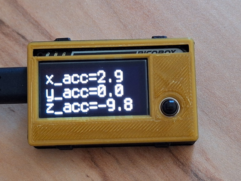
Es kann jetzt ein erster Test mit dem Beschleunigungssensor erfolgen. Zunächst wird das Display initialisiert und eine Textausgabe definiert.
Für die Funktion des Sensors wird in Zeile 10 'my_stk8ba58' importiert. Der Sensor selbst wird in Zeile 36 mit
sensor=my_stk8ba58.STK8BA58() definiert. Das kann so in jedem Programm, welches den ACC-Sensor beim PicoBoy nutzen soll, geschehen.
1  import time
2  import board
3  import busio
4  import displayio
5  import digitalio
6  import terminalio
7  import fourwire
8  from adafruit_display_text import label
9  import adafruit_displayio_sh1106
10 import my_stk8ba58
11
12 # Compatibility with both CircuitPython 8.x.x and 9.x.x.
13 # Remove after 8.x.x is no longer a supported release.
14 try:
15     from fourwire import FourWire
16 except ImportError:
17     from displayio import FourWire
18
19 # built-in a display
20 displayio.release_displays()
21 # Make the displayio SPI bus and the sh1106 display
22 spi = busio.SPI(board.GP18, board.GP19)
23 #
24 # Circuit 8.x.x
25 #display_bus = displayio.FourWire(spi, command=board.GP8, chip_select=board.GP10, reset=board.GP9, baudrate=1000000)
26 #display =adafruit_displayio_sh1106.SH1106(display_bus, width=132, height=64, rotation=0, brightness = 1)
27 #
28 # Circuit 9.x.x
29 display_bus = FourWire(spi, command=board.GP8, chip_select=board.GP10, reset=board.GP9, baudrate=1000000)
30 display =adafruit_displayio_sh1106.SH1106(display_bus, width=132, height=64, rotation=0, brightness = 1)
31 # Make the display context
32 splash = displayio.Group()
33 display.root_group = splash
34
35 # ACC-Sensor initialisieren
36 sensor=my_stk8ba58.STK8BA58()
37
38 # create the label
39 updating_label = label.Label(font=terminalio.FONT, text="Systemstart", scale=2, color=0xffffff, line_spacing=0.9)
40 updating_label.anchor_point = (0, 0)
41 updating_label.anchored_position = (1, 1)
42 splash.append(updating_label)
43
44 while True:
45     #read STK8BA58
46     val_1=sensor.xAcc()
47     val_2=sensor.yAcc()
48     val_3=sensor.zAcc()
49     wert_x = int(val_1 * 100)/10
50     wert_y = int(val_2 * 100)/10
51     wert_z = int(val_3 * 100)/10
52     updating_label.text = "x_acc="+str(wert_x)+"\ny_acc="+str(wert_y)+"\nz_acc="+str(wert_z)
53     time.sleep(0.5)
54
Geholt werden die Werte für xAcc, yAcc und zAcc ab Zeile 45 in der 'while-Schleife'. Sie werden in gerundeter Form
den Variablen wert_x, wert_y und wert_z zugewiesen und alle 0.5 Sekunden auf dem Display ausgegeben. Bewegt man nun
das Display in verschiedenen Richtungen, sieht man, wie sich die Werte ändern. 'It works !!'
Zum Abschluss noch eine kleine Zugabe, welche eine kleine Kugel auf dem Bildschirm hin- und herbewegt und in ein Loch versenkt werden muss. Mehr
wird an dieser Stelle mal noch nicht verraten. Probieren Sie es einfach aus, indem Sie den Quellcode in die Thonny-IDE kopieren und als
code.py speichern. So kann das kleine Beispiel auch ohne den Rechner mit externer Spannungsquelle oder bei eingelegter
Knopfzelle durch Betätigen des Schalters 'gespielt' werden.
1  import time
2  import board
3  import busio
4  import displayio
5  import digitalio
6  import terminalio
7  import fourwire
8  from adafruit_display_text import label
9  from adafruit_display_shapes.circle import Circle
10 import adafruit_displayio_sh1106
11 import my_stk8ba58
12 import random
13 import pwmio
14
15 # Compatibility with both CircuitPython 8.x.x and 9.x.x.
16 # Remove after 8.x.x is no longer a supported release.
17 try:
18     from fourwire import FourWire
19 except ImportError:
20     from displayio import FourWire
21
22 # built-in a display
23 displayio.release_displays()
24 # Make the displayio SPI bus and the sh1106 display
25 spi = busio.SPI(board.GP18, board.GP19)
26 #
27 # Circuit 8.x.x
28 #display_bus = displayio.FourWire(spi, command=board.GP8, chip_select=board.GP10, reset=board.GP9, baudrate=1000000)
29 #display =adafruit_displayio_sh1106.SH1106(display_bus, width=132, height=64, rotation=0, brightness = 1)
30 #
31 # Circuit 9.x.x
32 display_bus = FourWire(spi, command=board.GP8, chip_select=board.GP10, reset=board.GP9, baudrate=1000000)
33 display =adafruit_displayio_sh1106.SH1106(display_bus, width=132, height=64, rotation=0, brightness = 1)
34 # Make the display context
35 splash = displayio.Group()
36 display.root_group = splash
37
38 # ACC-Sensor initialisieren
39 sensor=my_stk8ba58.STK8BA58()
40
41 led_red = pwmio.PWMOut(board.GP7)
42 points=0
43 # create the label
44 updating_label = label.Label(font=terminalio.FONT, text="Punkte: " + str(points), scale=1, color=0xffffff, line_spacing=0.9)
45 updating_label.anchor_point = (0, 0)
46 updating_label.anchored_position = (35, 1)
47 splash.append(updating_label)
48
49 def pos_hole(x_hole,y_hole):
50     global hole
51     x_hole = random.randint(5,122)
52     y_hole = random.randint(5,58)
53     hole=[x_hole, y_hole]
54     circle_hole.x = x_hole
55     circle_hole.y = y_hole
56
57
58 xpos = 66
59 ypos = 32
60 x_hole = 0
61 y_hole = 0
62 circle_hole = Circle(x_hole, y_hole, 3,fill=0x000000, outline=0xffffff)
63 splash.append(circle_hole)
64 circle = Circle(xpos, ypos, 2,fill=0xffffff, outline=0x000000)
65 splash.append(circle)
66
67 hole=[0,0]
68 pos_hole(x_hole,y_hole)
69 print(hole)
70
71 while True:
72     #read STK8BA58
73     val_1=sensor.xAcc()
74     val_2=sensor.yAcc()
75     #val_3=sensor.zAcc()
76     wert_x = int(val_1 * 100)/10
77     wert_y = int(val_2 * 100)/10
78     if wert_y > 1 and xpos>=4:
79         xpos -= 3
80     if wert_y < -1 and xpos<=122:
81         xpos += 3
82     if wert_x > 1 and ypos<=56:
83         ypos +=2
84     if wert_x <-1 and ypos>=2:
85         ypos -=2
86     circle.x = xpos
87     circle.y = ypos
88     if abs(xpos-hole[0])<3 and abs(ypos - hole[1])<3:
89         #print(abs(xpos-hole[0]),", ",abs(ypos - hole[1]))
90         circle_hole.fill=0xffffff
91         points+=5
92         updating_label.text = "Punkte: " + str(points)
93         for i in range(3):
94             for cycle in range(0, 65535, +2):  # Cycles through the full PWM range from 0 to 65535
95                 led_red.duty_cycle = cycle  # Cycles the LED pin duty cycle through the range of values
96             for cycle in range(65534, 0, -2):  # Cycles through the PWM range backwards from 65534 to 0
97                 led_red.duty_cycle = cycle  # Cycles the LED pin duty cycle through the range of values
98         circle_hole.fill=0x000000
99         pos_hole(x_hole,y_hole)
100    time.sleep(0.1)
Viel Spass und Erfolg beim Ausprobieren.
Viel Spass und Erfolg beim Ausprobieren.